Burning Weeds
Burning weeds is fun. It may also be cost effective, easy to apply than chemicals and just feels more natural. My neighbor once described a brief pass over weeds as “instant drought”. Maybe, but it works well. That is, unless your burner stops working.
The burner hooks directly to a propane gas tank. You just need a regulator, a flow value, and a wand. Light a spark and you have a nice torch.
In my case, I couldn’t get any gas to flow. I messed around trying to dissemble everything and then used compressed air to clear any blockages. This didn’t work. I started looking at new wands. They were > 100$ and repairing this was worth trying, but I needed to understand how this tool worked.
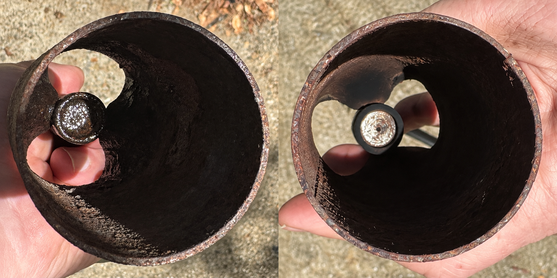
The key insight is that there is a small hole where the gas escapes. Mine was clogged. I put WD-40 on both sides of this hole and used a steel brush on my drill to clean this out and then compressed air until the blockage cleared. Next time, I won’t leave this wand out in the rain. Lesson learned.
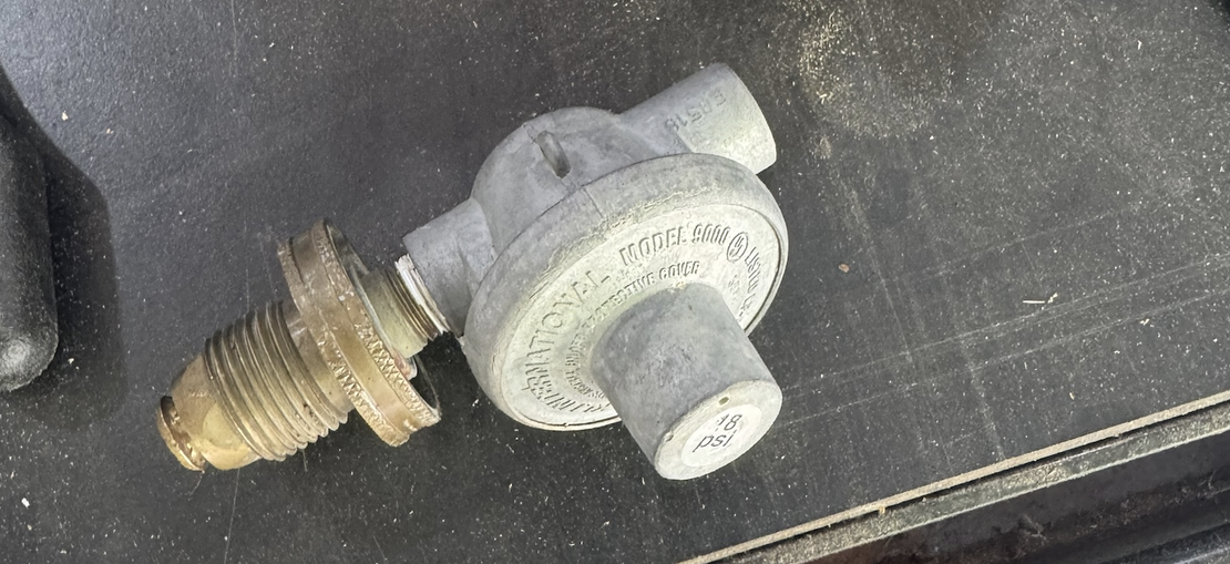
The regulator is wrist-watch cool, it’s a mechanical feedback loop
The first part to understand is the regulator. In a typical direct-operated reducing regulator, outlet pressure pushes on a flexible diaphragm while a spring supplies the opposing force. A linkage connects that diaphragm to a valve at a restricted passage. The valve changes the opening through which higher-pressure gas enters the lower-pressure side.
Open the torch’s control valve and gas leaves the downstream side. As outlet pressure falls, its force on the diaphragm falls; spring force moves the mechanism toward a larger opening. When demand decreases, outlet pressure rises and the mechanism throttles toward closed. At a steady demand, it settles near a balance. The regulator responds continuously; it is not a pump or simply an on/off switch.
I can’t follow paragraphs like this, so I built an illustration. Watch the linked diaphragm, stem and valve move together while the spring length changes. Motion is exaggerated to explain the feedback direction; this is not a pressure-response calculation.
A small fuel outlet inside a much larger cup
Flame Engineering describes a fitting welded to the pipe end with a pin-sized central orifice. This detail was critical to fix this. There is much power in building a 3d model of a part. You can explore exactly how things work and then do a very surgical fix. Professionals gain this knowledge over years in apprenticeships, but weekend hacks like me can get the same wisdom from a model.
First, pressure drives gas through the restricted outlet. The emerging jet transfers momentum to surrounding air, drawing air into the mixing region. Fuel and oxygen then burn, producing a nice focused torch. The large air openings and the small fuel opening perform different jobs.
The end of the wand is a mixing chamber, not a safety shield. The torch turns a narrow stream of propane into a broad flow of heat as it mixes in this tube. Pressurized fuel travels down the wand and accelerates through a small outlet into the burner bell, which is 2 inches (about 51 mm) across on the Weed Dragon VT2-23C. The fast-moving jet pulls surrounding air through the openings behind the bell a process called entrainment. The wider tube gives that air and fuel room to mix as the jet spreads. Once ignited, the mixture releases heat, expands, and continues mixing with outside air beyond the mouth, producing a flame much wider than the original fuel jet. The bell helps shape this flow, but the flame’s width and length also depend on fuel flow, air supply, and wind. The drifting haze in the illustration makes normally invisible gas motion visible.
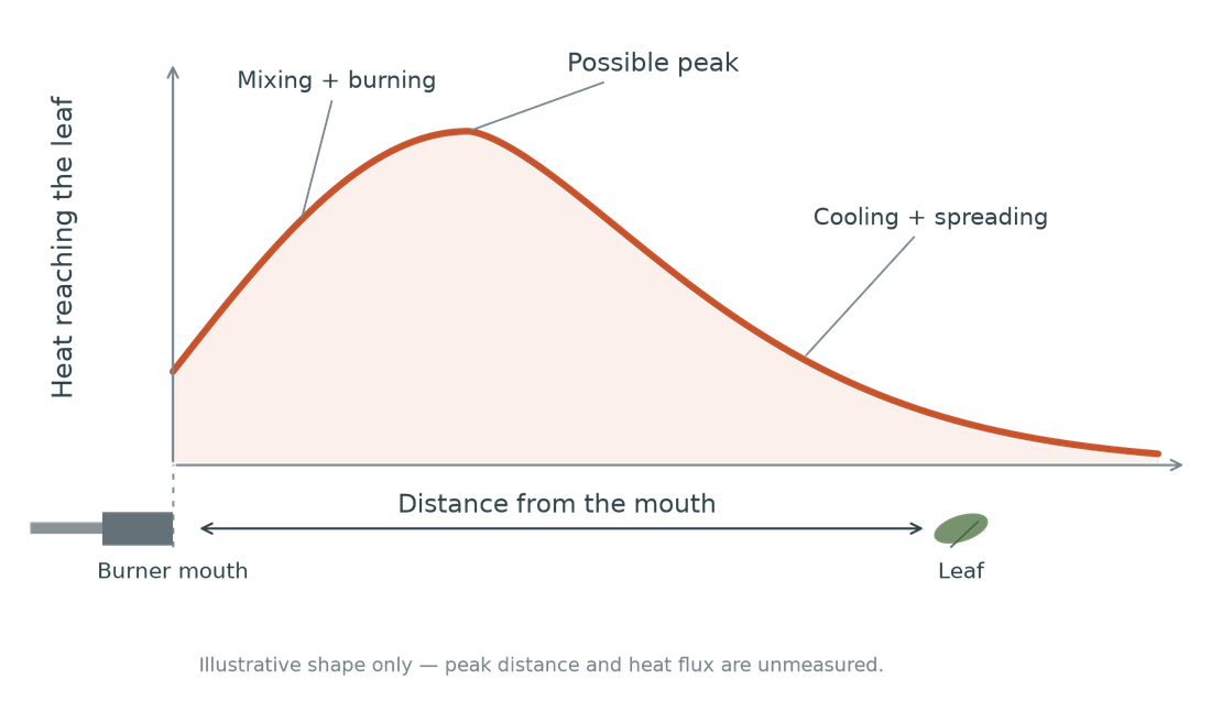
The heat does not necessarily peak at the burner’s face, and it does not simply fall as \(1/\text{distance}^2\). Near the torch, combustion, mixing, and the hot gas striking a surface all affect heat delivery. To understand the chemistry and the heat, let’s use NASA’s explanation of flame color. Blue in a real flame comes largely from light emitted by excited molecules during combustion. It is not a “cool” region. Yellow, orange, and red often come from glowing soot particles. Brightness and color alone cannot tell us the gas temperature or how much heat reaches a leaf.
The heat is not maximized at the end of the wand where fuel may still be mixing and burning. It takes distance for the reaction to increase. Farther downstream, the jet spreads, entrains cooler air, and loses speed and temperature. The concept here is heat flux:
Practically, this means you need to experiment on distance.
Why does a short pass of heat kill plants?
The trivial answer is that if you turn a plant into ash, it’s gone. That isn’t the idea here. I’ve learned a light pass that causes just a little wilt is best.
How does a pass of high heat kill a plant? A healthy leaf’s firmness depends partly on turgor: water pressure within living cells pressing against their walls. Membranes maintain the separation and chemical gradients that make normal cell function possible.
The plant dies when damage exceeds its capacity to sustain itself and rebuild. Loss of support for the roots is part of that process, but damage to the growing points also matters.
Heat damages membranes and proteins, causing cells to lose function and water pressure. Leaves wilt and lose their ability to produce sugars that support the roots and new growth. The plant can recover if surviving leaves and stored reserves sustain it long enough for living buds to produce replacements. If that recovery fails, or heat destroys the growing points needed for replacement, the damage becomes fatal.
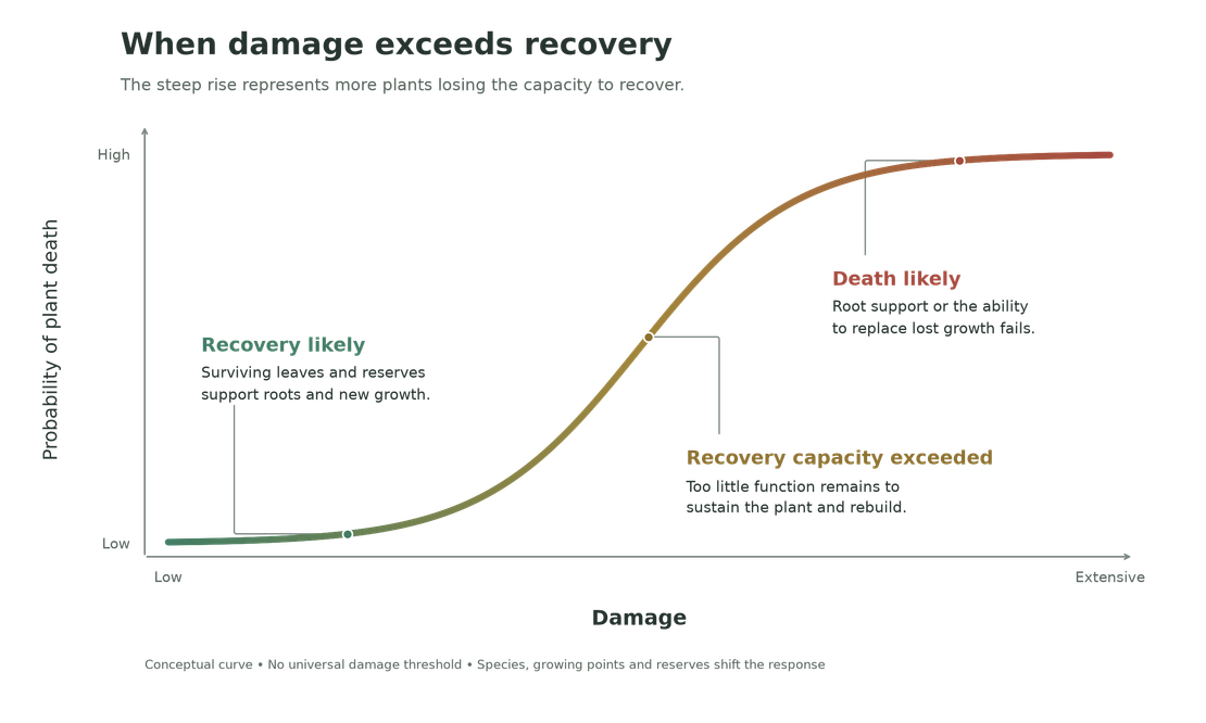
The S-curve describes how increasing heat exposure pushes more plants beyond that recovery limit. At low doses, most recover. Through the steep middle, more sustain fatal damage. At high doses, most susceptible plants have already crossed the limit. There is no universal percentage of leaf loss that kills every plant; protected buds and stored reserves change the outcome. Also, a curve measuring reduced growth must not be mistaken for a curve measuring death.
To do it right, pass the heat across the foliage and exposed growing points, the tips or buds producing new leaves. Burning through the stem could work if you really destroy it but that takes too much time.
From my reading on this, a good field check is to let the treated leaf cool, then gently press it between thumb and finger. A lasting thumbprint, dark watery appearance, or easily crushed tissue indicates sufficient heat injury in that area.
Why the same treatment can kill one weed and spare another
Burning doesn’t affect all plants equally. Small broadleaf seedlings are often susceptible because their growing points are exposed. Grasses can protect those growing points near the soil or within leaf sheaths. Established perennials can retain roots, crowns or underground stems that produce another shoot after the visible foliage is injured. A wilted top is not proof of a dead root system. [9] [11]
Nebraska experiments found that response changed with propane dose, species, growth stage and time of day; grasses generally tolerated more flaming than broadleaf species. So a universal pass speed or a single exposure will not kill every weed. [10]
Flaming also has practical limits. It is nonselective, can injure desirable plants, and can ignite dry vegetation or mulch. (Ask my wife about lighting the house on fire.) [9]
The useful question is not “How completely did I burn it?” It is whether enough vulnerable living tissue was injured to prevent recovery, and whether protected growing points can still restart growth. Several fast passes are a good experimental way to find out.
Sources & model notes
- Flame Engineering: 18 psi high-pressure regulator
- Flame Engineering: Weed Dragon specifications
- Emerson: Self-operated regulators
- Emerson: Direct-operated regulator force balance
- Flame Engineering: Orifice identification FAQ
- US patent 3357474: Related historical burner; not this model’s internal drawing
- University of Nebraska–Lincoln: Flame-weeding research
- Nebraska CropWatch: Thermal injury mechanisms
- Iowa State University: Flame weeding and plant response
- Ulloa, University of Nebraska–Lincoln: Flaming response research dissertation
- University of Maryland Extension: Managing weeds without chemicals
- OpenStax Biology: Water transport and turgor