Fixing the inlet on my Ryobi Pressure Washer
Some posts I write to inform others of cool stuff. Others posts I write to save someone else time when they google. This post is just a story of frustration, written to look like the second example. You have been warned.
Several years ago, I bought this pressure washer and then let it sit unused for far too long—a bad move. The Ryobi RY80940B, powered by a Honda GCV190 engine, delivers 3,100 PSI at approximately 2.5 GPM, more than enough force for serious cleaning but also enough to punish neglected hardware. For anyone working on one of these, the operating manual is available here: Ryobi RY80940B Service Manual (PDF).
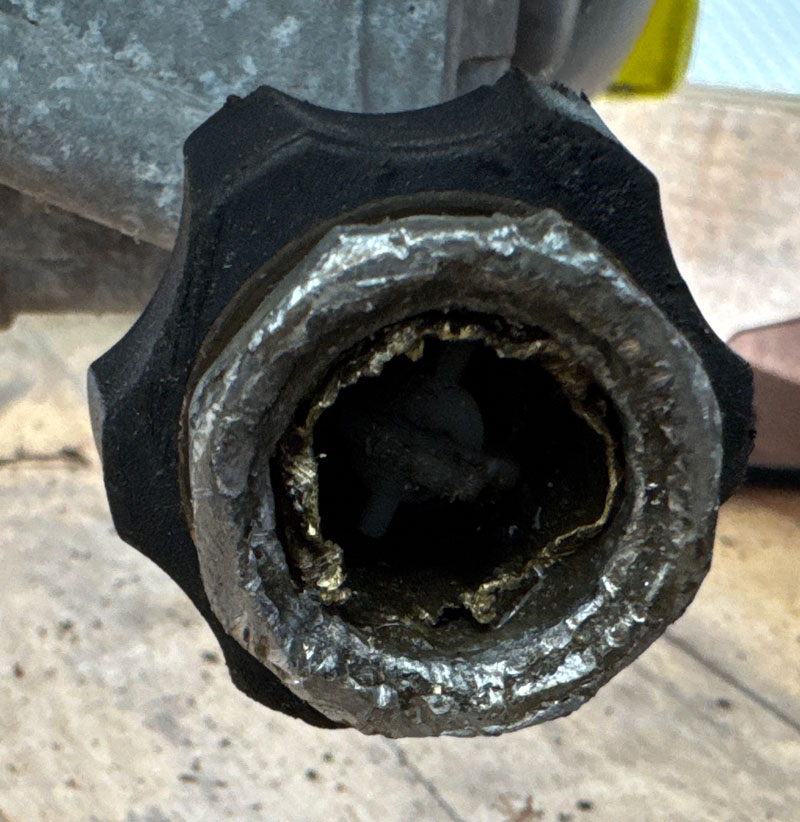
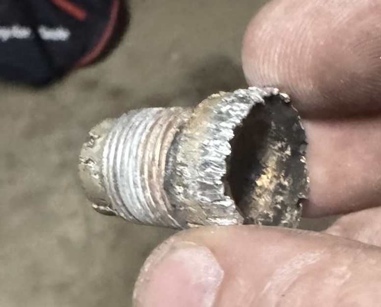
When I finally tried to remove the hose, the metal fitting was stuck. The smart thing would have been to leave the hose stuck in there forever. I didn’t do that. I wanted to get the old hose out and, well, I’m an arrogant engineer and this was a battle of wills not of wits. I’ve spent the better part of an afternoon fighting with a broken brass fitting fused inside the outlet coupler of my Ryobi RY80940B pressure washer. What should have been a simple hose replacement turned into a problem. The brass insert from the old high-pressure hose sheared off cleanly, leaving a ring of corroded metal wedged inside the plastic spindle. I tried everything — prying, tapping, a bolt extractor — but the brass just spun or smeared instead of breaking free.
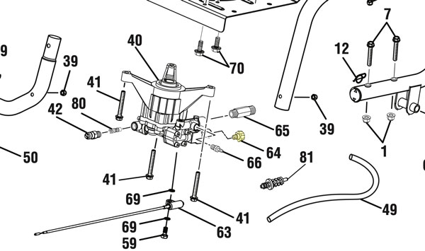
Eventually, I realized I was wasting time trying to rescue a part that costs less than lunch. The black collar that covers the quick-connect doesn’t unscrew; it slides over a spring and bearing set. Once you see the parts diagram for this model, it’s obvious the spindle (part #642058001) and collar (part #310993003) are meant to be replaced together.
Per the service manual, I first tried an 8 mm hex key to back out the fitting, but it immediately began to strip, producing nothing but a rain of metal shavings.
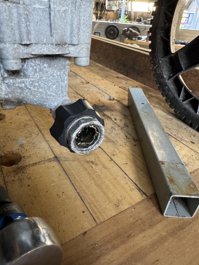
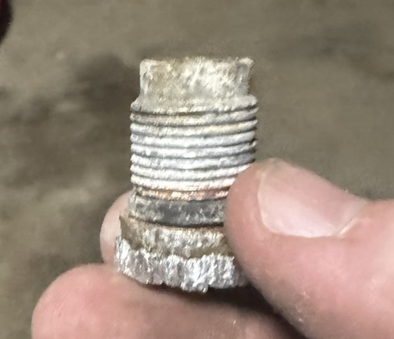
After exhausting every polite method of extraction, I escalated. Since I knew the brass and aluminum had fused completely, I cut most of the seized coupler off with an angle grinder, then used diagonal cutters to peel the remaining sleeve away from the spindle. With the bulk removed, I applied heat from a torch, clamped a pair of vice grips onto what was left, and added a four-foot cheater bar for leverage. The grips slipped off more than once, but eventually I felt the faint give of motion—the threads finally broke free. Sometimes the “fix” isn’t surgical precision; it’s controlled brutality, executed carefully enough not to destroy the surrounding parts.
Because this took so much work. I’m going to show you two pictures.
Tech Details
So what happened here? The failure wasn’t merely mechanical — it was electrochemical and thermomechanical. The brass hose insert (nominally Cu–Zn alloy, ≈ \(Cu_{60}Zn_{40}\)) had been pressed into a steel spindle (Fe–C alloy with minor Mn, Si). Over years of intermittent water exposure, this dissimilar-metal couple set up a galvanic cell with the water acting as electrolyte. Brass is more noble than steel in the galvanic series:
$$E^\circ_{\text{Cu}^{2+}/\text{Cu}} = +0.337\text{ V}, \quad E^\circ_{\text{Fe}^{2+}/\text{Fe}} = -0.440\text{ V} $$
The potential difference,
$$\Delta E = E_{\text{cathode}} – E_{\text{anode}} \approx 0.777\text{ V},$$
was sufficient to drive anodic dissolution of iron and the formation of iron oxides/hydroxides.
The local electrochemical reactions were:
Anode (steel):
$$\text{Fe} \rightarrow \text{Fe}^{2+} + 2e^-$$
Cathode (brass surface):
$$\text{O}_2 + 2H_2O + 4e^- \rightarrow 4OH^-$$
The resulting \(Fe(OH)_2\) and \(Fe_2O_3\) corrosion products expanded volumetrically, wedging the interface tighter. The growth strain of oxide formation can be expressed as:
$$\varepsilon_v = \frac{V_{\text{oxide}} – V_{\text{metal}}}{V_{\text{metal}}}$$
For iron oxides, \(\varepsilon_v \approx 1.9\), meaning nearly a doubling in volume. This expansion induced radial compressive stress at the interface:
$$\sigma_r = \frac{E \, \varepsilon_v}{1 – \nu}$$
With \(E_{\text{Fe}} \approx 210\,\text{GPa}\) and \(\nu \approx 0.3\), localized stresses easily exceeded hundreds of MPa, enough to plastically deform the surrounding brass and produce microscopic cold-welding through diffusion and oxide bridging.
At the same time, dezincification occurred in the brass:
$$\text{CuZn} \rightarrow \text{Cu} + \text{Zn}^{2+}$$
leaving a porous copper-rich layer with high surface energy. Under compression and mild heat cycling, solid-state diffusion across the Cu–Fe interface promoted the formation of intermetallic compounds such as \(CuFe_2\) or \(Fe_3Zn_{10}\), effectively brazing the two metals together.
The end state was a compound joint bonded both by corrosion-product expansion and diffusion adhesion — a quasi-metallurgical weld. The torque required to shear it loose later had to exceed the yield strength of both alloys plus the adhesion energy of the oxide layer:
$$\tau_{\text{break}} \ge \frac{\sigma_y A + \gamma_{\text{adh}}}{r}$$
where \(\sigma_y\) is the yield stress, A the contact area, \(\gamma_{\text{adh}}\) the oxide interfacial energy, and r the effective radius. I estimate I needed breakaway torque of in the neighborhood of 80–160 N·m, danger close to the ~200-250 N·m that will break a Grade 8.8 M16 bolt — and this was a thin walled threaded tube. The geometry also doesn’t help. Since brass (CuZn) was threaded into the aluminum/steel pump body at M16 scale, the fine 1.5 mm pitch meant very tight thread flank contact. Over years of water exposure, galvanic corrosion products grew in the tiny 60° V thread roots, effectively cold-welding the joint.
So the “fused” fitting wasn’t rusted in the casual sense — it had become a galvanic, mechanically locked, diffusion-bonded composite system, obeying the same physics that make bimetallic corrosion joints and accidental cold-welds in space so hard to undo.