This post is about how to use design tools to save time and build nice stuff at home using computer controlled machines (CNC). In addition to describing my design process, I’ve also included the helpful references I found along the way.
Our old thermostat was too small for our wall. I could have replaced the drywall, but I needed a starter project to help me understand 3D CNC work with wood. Replacing the drywall would have taken a good bit of time because of the lath behind the old thermostat. The bracket took a long time because I had to learn wood CNC and spent way too long finishing the surface. In the end, this was a great use of a wood CNC machine. It would have been difficult to get the corners right and route out the pocket inside. Additionally, I could prototype and correct parts of my design with the rapid iteration that CNC machines provided.
We have a programmable thermostat with z-wave, the 2gig CT100 Z-Wave Touch Screen Programmable Thermostat. It works perfectly and is easy to control with our Mi Casa Verde VeraLite Home Controller. This gives us the ability to set our temperature from our phones or do nest-like things like learn our patterns and adjust temperature. We can also set up multiple thermostats to regulate temperature throughout the different regions of our house.
In case you are working with the CT100 or the VeraLite, you might find the following links helpful:
- First I measured the thermostat from the manual.
- nice install video
Design
I designed the bracket in Fusion 360. I’m still figuring out how to use Fusion, but it is a computer-aided design application for creating 3D digital prototypes including design, visualization and simulation. Fusion 360 is easy to use and it provides the ability to go from design, render, analysis and production in one tool. Most important, it is free for hobbyists.
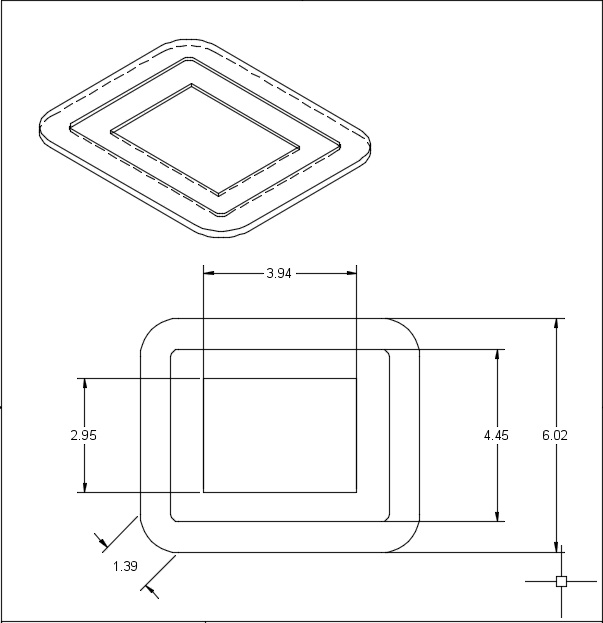
The design was pretty straightforward. It is a one inch offset with fillets that matched the radius of the CT100. One problem with CNC routing is that I tend to design features that take advantage of the CNC features and this tends to lead to more curves. I just had to get the measurements right. I shouldn’t need to do this, but I used a laser cutter to cut out the frame from a piece of cardboard to check the fit. I’m glad I did, because I hadn’t accounted for some of the curves and the opening was too small. In general, I love using the laser-cutter to prototype designs. The prototype let me see how the final design would look on the wall. This would have been helpful to test different designs. Chrissy and I tend to like 18th-century English and 19th-century neoclassic millwork, but I didn’t put too much thought into this design, partly because I could change it so easily.
Here is the final, dimensioned, design:
Construction
I found a piece of scrap plywood at TechShop that I cut on the ShopBot buddy.

To cut the workpiece I used the 1/4″ High Speed Steel Two Flute Downcut. You can see the purchase page here. As this was my first cut, I had to understand the definitions and the different cutter parameters to build the tool in fusion.
For the High Speed Steel Two Flute Downcut I have the parameters are:
- CED: 1/4
- CEL: 1
- SHK: 1/4
- OAL: 3
Here are some terms that helped me:
CED: CED is abbreviated for cutting edge diameter or the width of the cut the tool should make through the work piece. CED has a tolerance in thousandths of an inch or .xxx decimal places.
CEL: CEL is abbreviated for cutting edge length and is the maximum thickness of the material it can cut. CEL has a tolerance in hundredths of an inch or .xx decimal places.
SHK: SHK is abbreviated for shank diameter and is the nominal size of the shank which should match the collet size of the spindle the tool will be used in. SHK has tolerance in the ten-thousandths of an inch or .xxxx decimal places.
OAL: OAL is abbreviated for overall length and is the total nominal length of the tool from end to end. OAL has a tolerance in hundredths of an inch or .xx decimal places.
HSS: High Speed Steel, typical applications in Non-Abrasive Plastic, Solid Wood & Aluminum where keen edges perform best. High Speed Steel tools perform well in hand routing applications where a tough core is necessary to prevent tool breakage.
Carbide Tipped: Used for a variety of applications in composite woods, hardwoods, abrasive plastics and composites plastics to hard aluminum. Limited by geometry in some applications due to the brazed nature of the tool. Carbide Tipped tools work well in hand routing applications due to the tough HSS core and hard carbide cutting edges.
Solid Carbide: Typically used for widest variety of applications including man-made board, solid wood, abrasive plastics, and some aluminum’s. Solid Carbide does not deflect allowing the tool to be fed at higher feedrates than PCD or straight insert cutters decreasing cycle times. s typically. Solid tools also have major edge keenness advantage thought only possible in HSS until a few years ago.
Chipload: Chipload is simply defined as the thickness of a chip which is formed during the machining of a material. Chipload is critical because if the chip is the proper size, the chip will carry away the heat promoting long tool life. If the chip is too small, the heat is transferred to the cutting tool causing prematurely dulling. Too high of a chipload will cause an unsatisfactory edge finish, or part movement.
The most important reason to understand cutter parameters, is to set the correct feed rates, which is a combination of rpm and cutting speed. In order to get this right, I consulted this reference from ShopBot and read up on end mills in general at makezine. I also was able to incorporate some information from destiny tool that was helpful to verify my settings.
These links also helped:
* hardwood cutting data from Onsrud
* A great video tutorial from ShopBot
After understanding endmills, I had to get everything in the right format for the machine. I found the open sbp reference to be very helpful and the command reference also taught me how to understand the resultant g-code.
I summarized my research below:
Table
| Name | SB# | Onsrud Series | Cut | Chip Load per leading edge | Flutes | Feed rate (ips) | RPM | Max Cut |
|---|---|---|---|---|---|---|---|---|
| 1/4″ Downcut Carbide End Mill | 13507 | 57-910 | 1 x D | 0.005-0.007 | 2 | 3.0-4.2 | 18,000 |
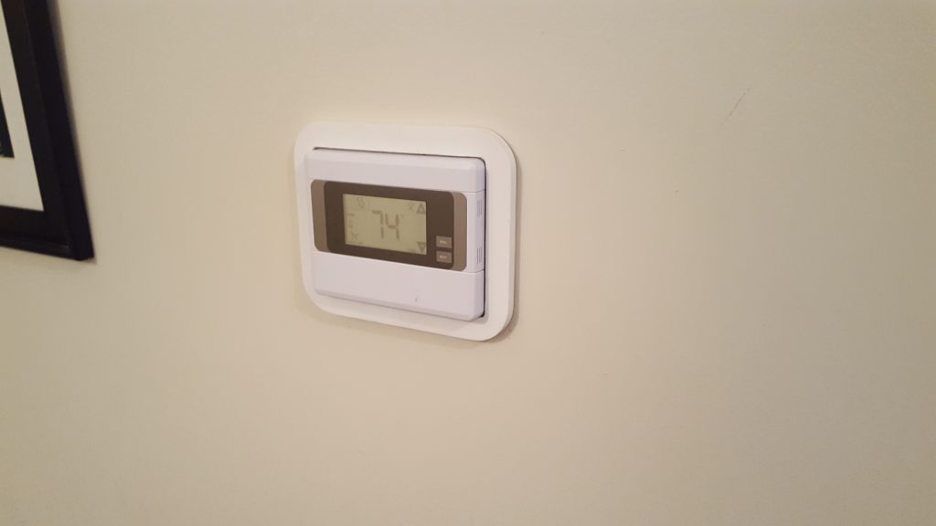
You can see the final product here:


This is awesome!